AMAC Pneumatic and Hydraulic Clamp Components Automated Machine Accessories Clamps
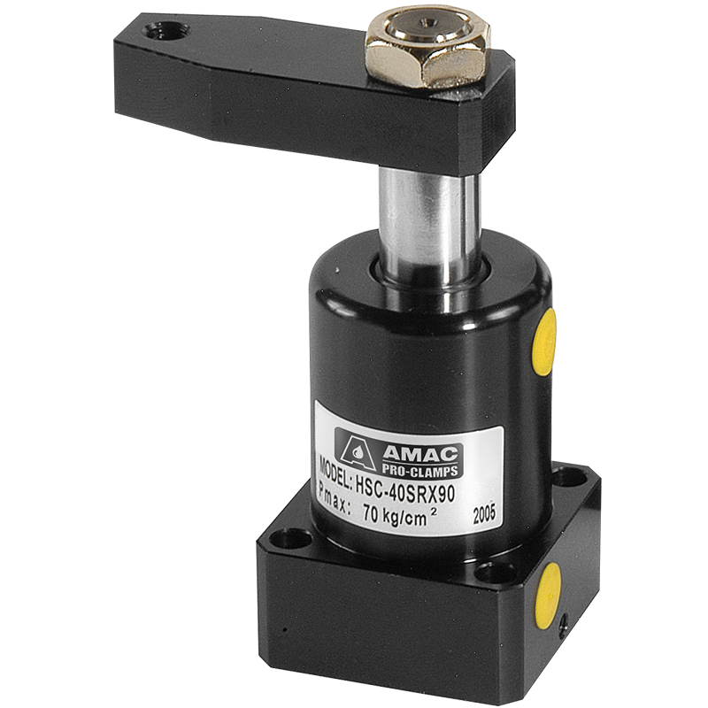
Product Introduction
• Bore : ø25~ø63 mm • Pmax : 100 Kg/cm²
• The product is ideal for mass production on a special purpose machine and jig on machining center. It will greatly upgrade production efficiency.
• When the hydraulic cylinder actuate, and the piston moves downward, the clamping arm will swing to a rated angle. Then it lowers until the workpiece is clamped securely.
• To avoid too fast motion a flow control valve is suggested to connect to the hydraulic swing clamp cylinder. Do not clamp workpiece while the calmp is swinging to avoid damaging on the cylinder barrel and internal parts.
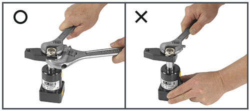
• When increasing length of clamping arm is required, be sure do not exceed 1.5 times of the original length.
• The cylinder body is manufactured from structural carbon steel. Surface is specially treated for maximum smoothness on inside surface and long service life.
Hydraulic Swing Clamp Product type

Product Introduction
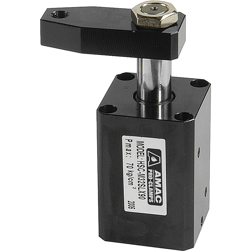
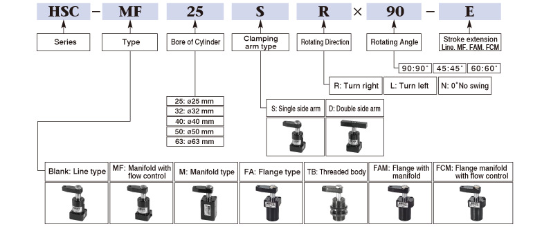
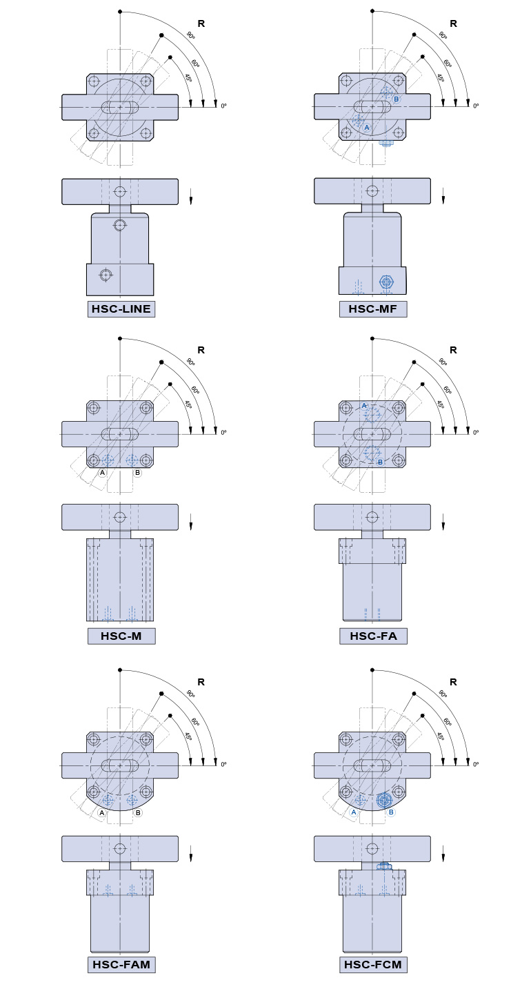
M: Manifold type
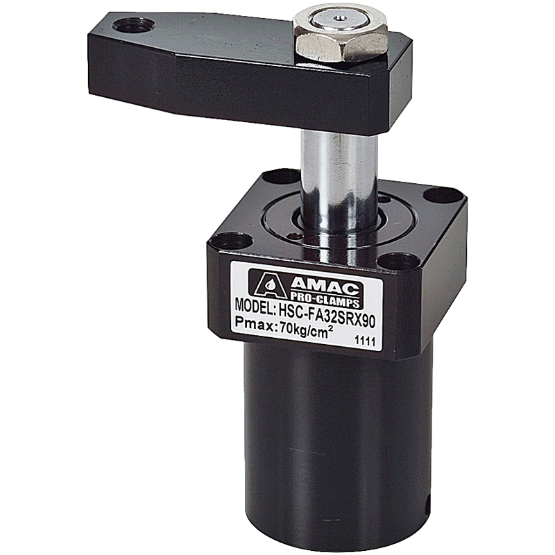
FA: Flange type
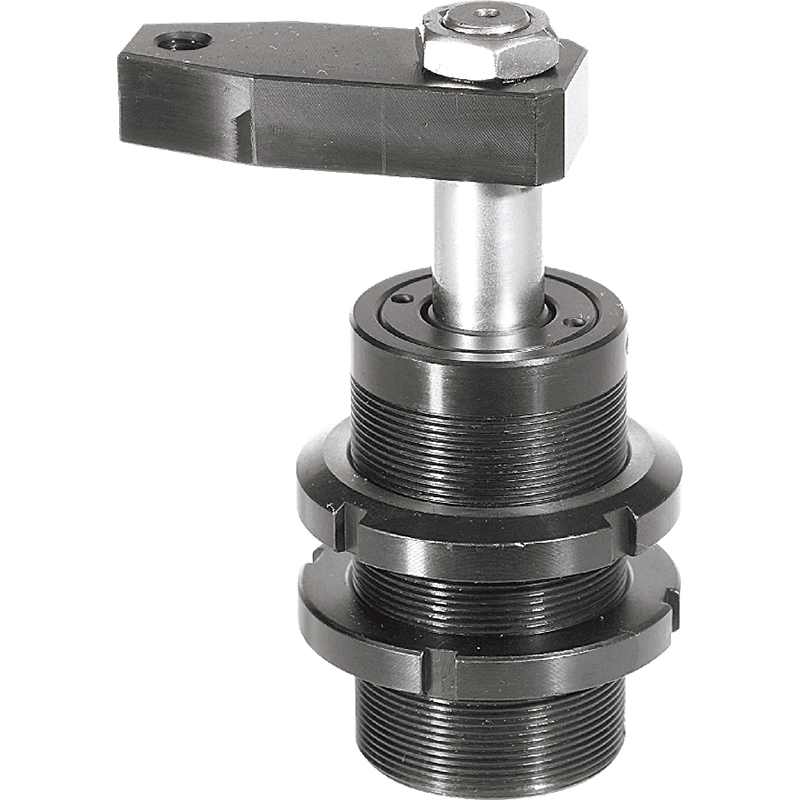
TB: Threaded body
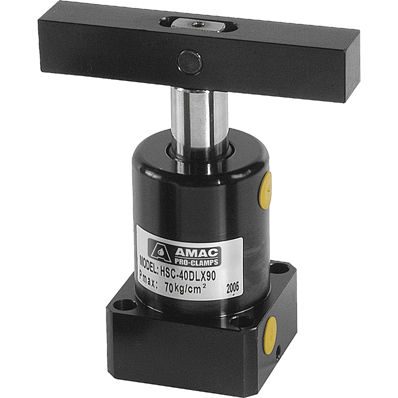
Line type (Double side clamping arm)
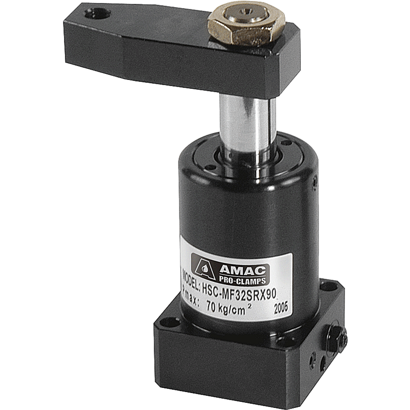
MF: Manifold with flow control
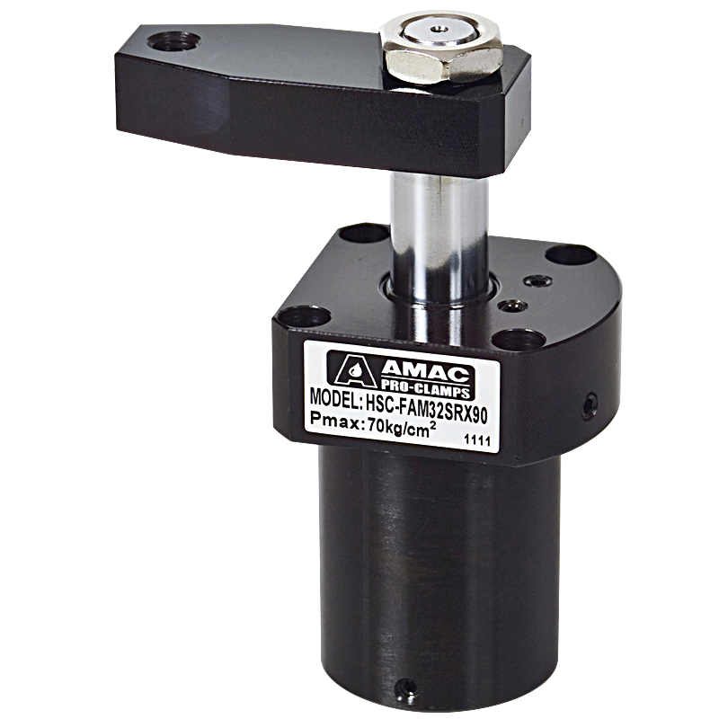
FAM: Flange with manifold
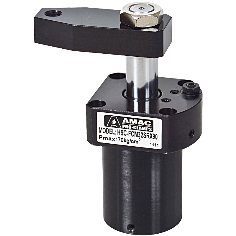
FCM: Flange manifold with flow control
Specification
| Bore of cylindermm | ø25 | ø32 | ø40 | ø50 | ø63 |
| Piston rod diametermm | ø18 | ø20 | ø22.4 | ø28 | ø35 |
| Swing strokemm | 9 | 11 | 11 | 13 | 13 |
| Clamping stroke (std/extension)mm | 13 | 15 / 30 | 15 / 30 | 17 / 34 | 17 / 34 |
| Pressure area(pull/push)mm | 2.37 / 4.91 | 4.9 / 8.04 | 8.63 / 12.57 | 13.47 / 19.63 | 21.55 / 31.17 |
| Theoretical clamping30 Kg/cm² | 71 | 147 | 259 | 404 | 647 |
| Fluid | Filtered air | ||||
| Max operation pressure | 100 Kg/cm² | ||||
| Operation pressure range | 5-7 Kg/cm² | ||||
| Rotating direction | R:Turn right/ L:Turn left/ N: 0˚ No swing | ||||
| Rotating angle | Standard angle 90˚, Optional angle 45˚, 60˚ | ||||
| Acting type | Double acting | ||||
Order Code
